
MATERIALS, PROTECTIVE COATINGS & CORROSION
Engineering materials are produced by changing naturally occurring minerals, metals, and chemical feedstocks into controlled compositions and structures. Steel is reduced from iron ore, aluminum is refined from bauxite, zinc is recovered from sulfide ore, and concrete is produced by reacting manufactured cement with water and aggregate. The resulting composition, microstructure, porosity, surface condition, and geometry influence how each material behaves in service.
Corrosion and coating failure are therefore closely connected to manufacturing. The same alloying elements that strengthen a metal can create local electrochemical differences. The same pores that form during concrete curing can later carry water and chloride toward reinforcing steel. A coating can delay those processes, but its performance depends on surface preparation, formulation, application, cure, thickness, and the environment it is expected to resist.
How Engineering Materials Are Made
A finished component carries the history of the processes used to make it. Refining establishes chemical composition; casting, rolling, extrusion, heat treatment, welding, and curing establish structure and geometry; fabrication establishes edges, seams, residual stresses, and surface condition. These features later influence corrosion, coating adhesion, and the locations where deterioration begins.
| Material | Production Route | Important Service Failure Modes |
|---|---|---|
| Structural steel | Iron-ore reduction or scrap melting, refining, alloying, casting, rolling, and fabrication | General corrosion, crevice corrosion, section loss, pack rust, and coating-underfilm corrosion |
| Zinc sheet | Ore concentration, roasting, leaching, purification, electrowinning, alloying, and rolling | Atmospheric corrosion, white corrosion, chloride attack, and galvanic attack from dissimilar metals |
| Aluminum alloy | Bayer refining, Hall-Héroult reduction, alloying, casting, rolling or extrusion, and heat treatment | Pitting, intergranular attack, exfoliation, and galvanic corrosion |
| Reinforced concrete | Clinker production, cement grinding, mixing with water and aggregate, placement, consolidation, and curing | Freeze-thaw damage, carbonation, chloride-induced reinforcement corrosion, cracking, and spalling |
Structural Steel: From Iron Ore to Bridge Girder
Structural steel begins with iron-bearing feedstock. In an integrated steelmaking route, iron oxides such as hematite and magnetite are reduced in a blast furnace. Coke supplies both heat and carbon monoxide, which removes oxygen from the iron oxides. Limestone reacts with unwanted mineral constituents and helps transfer them into slag. The product is molten iron with a carbon content that is too high for most structural applications.
A basic oxygen furnace lowers the carbon content and removes selected impurities. Alloying additions such as manganese, chromium, nickel, and molybdenum are then controlled to obtain the required balance of strength, toughness, hardenability, weldability, and corrosion behavior. Electric-arc-furnace steelmaking reaches the molten state by using graphite electrodes to melt scrap steel, direct-reduced iron, or mixed metallic feedstocks. Chemistry is adjusted before the steel is cast.[1][2]

Continuous casting converts the refined liquid steel into slabs, blooms, or billets. Rolling then reduces these shapes into plate, sheet, bar, rail, and other products. A bridge girder may be fabricated from plate by cutting a web and flanges, fitting them together, and welding the assembly into an I-shaped section. Heat treatment, cold working, welding, and forming can further alter the metal’s microstructure and residual-stress state.
These manufacturing steps matter to corrosion because they determine alloy chemistry, inclusions, grain structure, weld zones, surface scale, edges, crevices, and the condition of the surface that will later be coated.
Zinc: From Sphalerite to Roof Sheet and Gutter
Zinc is commonly recovered from sphalerite, a zinc-sulfide mineral. The ore is crushed and ground so the zinc-bearing particles can be separated from surrounding rock. Froth flotation concentrates the zinc mineral by attaching selected particles to air bubbles and carrying them to the surface of a flotation cell.
The concentrate is roasted in air, converting much of the zinc sulfide to zinc oxide while sulfur leaves primarily as sulfur dioxide. Sulfuric acid dissolves the zinc oxide into a zinc-sulfate solution. After purification removes unwanted dissolved metals, electrowinning deposits metallic zinc onto cathodes. The recovered zinc is stripped, melted, cast, and then converted into finished forms.[3]
Architectural zinc sheet is commonly alloyed with small amounts of copper and titanium, then rolled into coil and formed into roof panels, flashing, gutters, and downspouts. Alloying and rolling improve strength and dimensional stability while retaining the atmospheric corrosion behavior that makes zinc useful as an exposed architectural material.
Aluminum: From Bauxite to Aircraft Sheet

Aluminum production begins with bauxite. In the Bayer process, crushed bauxite is digested in hot sodium hydroxide so aluminum-bearing compounds dissolve while much of the iron oxide and other insoluble material is separated. Aluminum hydroxide is precipitated from the clarified solution and calcined to remove chemically bound water, producing alumina, Al2O3.[4]

The Hall-Héroult process converts alumina to metallic aluminum. Alumina is dissolved in a molten fluoride electrolyte and direct current drives the electrochemical reduction. Liquid aluminum collects in the cell while carbon anodes are consumed. The primary metal is then alloyed with elements such as magnesium, silicon, copper, manganese, or zinc to obtain the required strength, formability, castability, heat-treatment response, or electrical properties.
Aircraft sheet is produced by casting and rolling aluminum alloy into plate or coil, followed by combinations of solution heat treatment, quenching, stretching, aging, forming, machining, drilling, and fastening. Different alloy families and heat treatments create different microstructures. Those differences are central to both mechanical performance and susceptibility to localized corrosion.
Reinforced Concrete: From Mineral Feedstocks to Structural Composite
Portland cement is manufactured from calcium-, silicon-, aluminum-, and iron-bearing raw materials, commonly including limestone and clay. The raw materials are crushed, proportioned, and heated in a rotary kiln to approximately 1,450 °C. Carbon dioxide and water are driven off and the remaining solids react to form clinker minerals. The clinker is cooled and ground with a small amount of gypsum to make cement.[5]
Concrete is produced by combining cement with water, fine aggregate, and coarse aggregate. Water initiates hydration reactions that form new solid phases and bind the aggregate into a rigid composite. Reinforcing steel is embedded where tensile capacity is required. Placement, consolidation, water-cement ratio, cover depth, and curing determine pore structure, cracking tendency, and the ease with which later contaminants can move through the hardened concrete.
Concrete is therefore not simply a chemically inert shell around reinforcing steel. It is a porous, reactive material whose production and curing history strongly influence long-term transport of water, chloride, carbon dioxide, and other species.
How Engineering Materials Fail in Service
Material degradation is controlled by both the environment and the structure created during manufacture. Moisture provides an electrolyte for metallic corrosion, chloride destabilizes passive films, dissimilar metals create galvanic couples, and transport through concrete pores can bring aggressive species to reinforcing steel. Damage is often localized at joints, edges, pores, inclusions, grain boundaries, cracks, and other features that differ from the surrounding material.[6]
Structural Steel: Electrochemical Corrosion and Section Loss

The iron in steel is thermodynamically capable of returning to oxidized forms when an electrochemical cell develops. A corrosion cell requires an anodic region, a cathodic region, an ionic path through an electrolyte, and an electronic path through the metal. At the anode, iron is oxidized and leaves the metal as ferrous ions:
The released electrons move through the steel to cathodic regions. Under ordinary aerated wet conditions, dissolved oxygen can be reduced according to:
Ferrous ions and hydroxide participate in subsequent reactions that form iron hydroxides, oxyhydroxides, and oxides. These corrosion products are collectively observed as rust. Ordinary rust on structural carbon steel is generally not a dense, perfectly protective film; it can crack, retain moisture and salt, and expose new steel to repeated attack.[6][7]
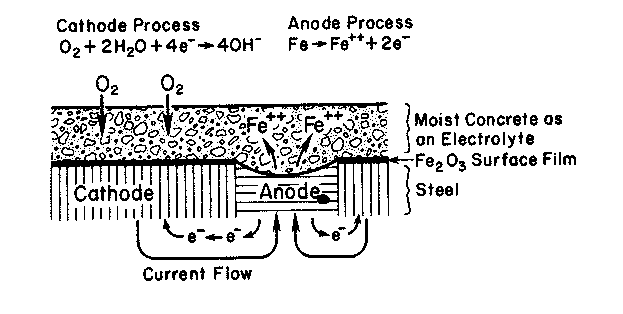
The anodic and cathodic regions may exist on the same piece of steel. Differences in oxygen access, moisture, chloride concentration, deposits, surface condition, and geometry can create local electrochemical cells. Bridge girders are particularly vulnerable beneath leaking joints, around drains, at seams and bolted connections, on horizontal ledges, and wherever debris retains salt-contaminated water.
Chloride increases electrolyte conductivity and can promote persistent localized attack. Repeated wetting and drying can reconcentrate salt at the same location. Continued metal loss thins webs, flanges, fasteners, and connection components. Corrosion products trapped between assembled plates can also generate expansive “pack rust” that forces plates apart.
Zinc: Protective Patina, White Corrosion, and Galvanic Attack
Zinc also corrodes electrochemically. At anodic areas, zinc dissolves according to:
Zn → Zn²⁺ + 2e⁻
Under ordinary atmospheric exposure, zinc corrosion products progress through oxides and hydroxides toward a surface layer containing basic zinc carbonate. When that patina becomes dense and adherent, it slows further reaction by restricting access of water, oxygen, and contaminants.
Persistent trapped moisture changes the process. Water beneath laps, inside poorly drained gutters, or under wet debris can limit access to fresh carbon dioxide and prevent development of the same stable carbonate-rich surface. Loose white zinc corrosion products can accumulate instead. Repeated wetting, dissolution, and removal consume the metal and can eventually produce thinning or perforation.[8]
Chloride, acidic contaminants, and sulfur-bearing pollutants can accelerate zinc loss. Contact with a more noble metal can concentrate attack further. Copper runoff or direct copper-to-zinc contact can create a galvanic cell in which the zinc becomes the anodic material and is consumed preferentially.[9]
Aluminum: Passive-Film Breakdown and Localized Corrosion
Aluminum normally develops a thin, adherent oxide film almost immediately after exposure to air. This passive film accounts for much of aluminum’s corrosion resistance. The principal concern is therefore not uniform oxidation of the entire surface, but localized breakdown of the oxide at defects or chemically aggressive sites.
Chloride-containing moisture can destabilize local regions of the passive film and initiate pits. Once a pit forms, hydrolysis of dissolved aluminum species can acidify the occluded solution. Chloride migrates into the pit to maintain charge balance, creating a chemistry that supports continued localized dissolution. A small surface opening can therefore conceal a deeper subsurface cavity.[10]
Alloy microstructure also matters. Copper-rich particles and other intermetallic constituents can form microscopic galvanic couples with the surrounding aluminum. Heat treatment, welding, or compositional segregation can produce susceptible grain-boundary regions. Attack along those boundaries can develop into intergranular corrosion or, in elongated wrought structures, exfoliation.
Larger galvanic couples occur when aluminum is electrically connected to stainless steel, copper, titanium, or carbon-fiber composite in the presence of an electrolyte. The severity depends on the materials, exposed area ratio, electrolyte, geometry, and persistence of wetting.
Reinforced Concrete: Transport, Cracking, and Reinforcement Corrosion
Hardened concrete contains a connected pore structure whose permeability depends strongly on mixture design, consolidation, curing, cracking, and service damage. Water moving through those pores can carry chloride, carbon dioxide, sulfate, and other species into the material.

Freeze-thaw deterioration develops when sufficiently saturated concrete is repeatedly exposed to freezing temperatures. Expansion and hydraulic or osmotic pressures within the pore system can progressively damage the cement paste and the paste-aggregate interface. Scaling and cracking then increase the rate at which later water and salt can enter.[11]
Carbonation occurs as carbon dioxide diffuses into moist concrete and reacts with alkaline cement-hydration products. The reaction lowers pore-solution alkalinity. If the carbonation front reaches the reinforcing steel, the passive condition normally maintained by high-pH concrete can be lost.[12]
Chloride from deicing salt or marine exposure can independently destabilize the passive film on reinforcement. Once corrosion begins, iron corrosion products occupy a larger volume than the metal consumed. The surrounding concrete restrains this expansion until tensile stresses cause cracking, delamination, and spalling. New cracks then accelerate access of water, oxygen, and chloride to the steel.[13]
Other internal deterioration mechanisms include alkali-silica reaction, in which reactive silica in aggregate forms a swelling gel in the presence of alkali and moisture, and sulfate attack, in which sulfate-bearing environments can drive formation of expansive or weakening reaction products.
How Protective Coating Systems Are Produced
Protective coatings slow deterioration by limiting the movement of water and chemicals, changing the surface of the material, or providing a metal that corrodes in place of the material beneath it. The material being coated is called the substrate. Performance depends on both the coating and the strength of its attachment, or adhesion, to that substrate.[14]
The following five systems protect materials in different ways. Galvanizing covers steel with zinc; anodizing grows a protective oxide layer from aluminum. Epoxy linings and powder coatings form polymer films, made of large molecules joined or held together. Multi-layer systems combine coatings with different functions. Each system is described below and revisited in the same order in the failure section.[15]
Hot-Dip Galvanized Steel

Hot-dip galvanizing begins with surface preparation. Steel is cleaned to remove oil and dirt, then treated with acid to remove rust and mill scale, the oxide layer left by hot steel processing. This acid-cleaning step is called pickling. After rinsing, a flux treatment helps keep the surface free of oxides and allows molten zinc to contact it. The prepared component is then immersed in molten zinc. At galvanizing temperature, iron from the steel reacts with zinc and produces layers of compounds containing both iron and zinc. A zinc-rich outer layer remains at the surface when the part is withdrawn and cooled.[16][17]
The coating protects steel both by acting as a physical barrier and by providing zinc that corrodes preferentially and helps protect small exposed areas of steel; this is called sacrificial protection. Coating thickness, steel chemistry, immersion time, drainage, geometry, and post-treatment influence the final galvanized structure.
Anodized Aluminum

Anodizing deliberately converts the outer region of aluminum into a thicker aluminum-oxide structure. Fabricated aluminum is cleaned and may be etched to remove a thin surface layer. Because alloying elements do not dissolve uniformly during etching, a desmutting step is commonly used to remove residual copper-, silicon-, iron-, or other constituent-rich material before anodizing.
In the anodizing bath, the aluminum workpiece is connected to the positive terminal of a direct-current power supply and immersed in an electrically conducting liquid, commonly a sulfuric-acid solution. Direct current drives oxide growth at the aluminum surface. The newly formed oxide is porous. Color can be introduced into those pores by dyes or by using electrical current to deposit coloring materials, after which the surface is sealed to reduce open porosity and improve resistance to entry of contaminants.
Unlike a deposited paint film, the anodic oxide is produced from the underlying aluminum itself and grows partly into and partly outward from the original surface.
Epoxy-Lined Steel

An epoxy lining starts with a resin, the main film-forming ingredient, and a curing agent, which reacts with the resin to harden it. The reaction forms chemical links between molecules, called cross-links, creating a connected solid network. This permanent chemical hardening is called thermosetting. Pigments, mineral fillers, glass flakes, ceramic particles, and other additives can change coating thickness, the ease with which water passes through it, resistance to rubbing or wear, chemical resistance, and appearance.
Steel intended for lining is commonly cleaned by propelling abrasive particles against it. This abrasive blasting removes corrosion products, mill scale, and contaminants and creates fine surface roughness that helps the lining bond. Liquid epoxy is mixed in the specified proportions and applied to the prepared steel, then allowed to cure under controlled time and temperature conditions. Fusion-bonded epoxy follows a different application route: the steel is preheated and a dry powder is applied, melted, flowed, and cured on the hot substrate.
AWWA C210 is one example of a specification governing liquid-epoxy coating systems for steel water pipe and fittings. The finished lining must remain continuous and adhered through application, handling, installation, and service exposure.[18][19]
The Ingredients in an Epoxy Lining
An epoxy lining is an organic coating, meaning its film-forming binder is based on carbon-containing compounds. Its ingredients have different functions. The same broad ingredient groups also appear in many powder coatings and multi-layer paint systems. The binder is the film-forming material that holds the coating together and binds pigment particles. Pigments are dispersed solid particles that can provide color, opacity, corrosion inhibition, or other properties. Solvents and water, where present, provide a liquid application medium and largely leave during drying. Additives adjust properties such as flow, settling, foaming, and resistance to ultraviolet degradation. Powder coatings deliver their film-forming ingredients without a liquid solvent carrier. [26, ch. 1; sec. 5.14]
| Ingredient | Function in the Coating | Connection to Performance |
|---|---|---|
| Binder | Forms the continuous film and holds dispersed particles together | Influences adhesion, flexibility, chemical resistance, and weathering behavior |
| Pigments and fillers | Provide color, opacity, bulk, or functional properties | Particle type, shape, amount, and dispersion influence barrier and mechanical properties |
| Solvent or water | Provides an application medium in liquid coatings | Evaporation and retention affect film formation; retained liquid can influence softness and blistering |
| Additives | Adjust specific formulation and application properties | Can control foam, flow, pigment settling, and resistance to degradation |
Pigment and Binder Balance: Why Formulation Matters
Pigment-volume concentration describes the volume of pigment relative to the combined volume of pigment and solid binder. At sufficiently high pigment loading, the binder becomes insufficient to wet the particles and fill the spaces between them. This transition is described by the critical pigment-volume concentration. In many barrier coatings, approaching or exceeding this concentration can make it easier for water and other substances to pass through the film and can reduce its strength or resistance to wear. The appropriate balance depends on the coating’s intended function; it is not a universal pass/fail limit for every coating type. [26, pp. 6–7]
Two coatings described as epoxy can therefore differ substantially in service. Resin chemistry alone does not establish performance: pigment loading, particle distribution, additives, cure, and the continuity of the finished film also matter.
Powder-Coated Steel
Thermosetting powder coating is manufactured by blending solid resin, curing agents, pigments, fillers, and additives. The blend passes through an extruder, a machine that heats and mixes it as it moves through a barrel. It is then cooled into a solid sheet or ribbon, broken into chips, and ground and sorted to obtain the required powder-particle sizes.
The steel component is cleaned and normally receives a pretreatment appropriate to the substrate and service requirement. In the coating booth, powder particles are electrically charged and sprayed toward a grounded workpiece. The electrostatic field helps retain the uncured powder on the surface. The part then enters an oven, where the powder melts, flows into a continuous film, and chemically cures.
Resin chemistry determines much of the final performance. Epoxy powders commonly provide strong adhesion and chemical resistance but limited long-term ultraviolet durability; polyester systems are widely used where exterior weathering is important. Surface preparation and pretreatment remain essential because a visually smooth cured film can still be poorly bonded to contamination or an inadequate pretreatment layer, the thin surface layer formed chemically before coating. ASTM D7803 addresses preparation of hot-dip galvanized surfaces for powder coating.[20]
Multi-Layer Coating Systems
Severe-service coating systems often use multiple layers. A structural-steel system may combine a zinc-rich primer (the first coat on the steel), an epoxy intermediate coat, and a polyurethane or polysiloxane topcoat (the exposed outer coat). Polyurethane and polysiloxane are families of polymer binders used in protective finishes. The primer contributes corrosion control at defects, the intermediate coat provides barrier thickness, and the topcoat contributes ultraviolet resistance, weatherability, color, and surface durability.
Other systems use zinc or aluminum melted and sprayed onto a surface, epoxy containing thin glass flakes to make water movement through the film more difficult, fusion-bonded epoxy with wear-resistant overcoats, or flexible membranes on concrete. In every case, the system contains multiple material interfaces. An interface is the boundary where two materials meet. Each must be clean and suitable for bonding. The next coat must also be applied within the specified recoat window, the permitted time between coats, or receive the required surface preparation before overcoating.
ISO 12944-6 reflects this systems approach by defining laboratory performance test methods used to assess protective paint systems for steel structures within its scope.[21]
How Protective Coating Systems Fail
Coating failure is not a single mechanism. A defect may originate during cleaning, pretreatment, mixing, application, cure, handling, installation, or service. External stresses such as ultraviolet radiation, abrasion, impact, chemicals, water, chloride, and temperature cycling can attack the film; corrosion and interfacial chemistry can attack from beneath it. Identifying the failure plane, the surface or layer where separation occurs, is often as important as describing the visible defect. The same five coating systems are examined below in the order used in the production section.
Hot-Dip Galvanized Steel
Zinc initially protects steel as both a barrier and a sacrificial metal. Reaction with air and moisture can form a relatively protective surface layer, called a patina. Near a small exposed steel area, zinc can dissolve and release electrons that help suppress corrosion of the steel.[22]
This protection is finite. Persistent chloride wetting, acidic or strongly alkaline exposure, mechanical wear, large bare areas, or long service can consume the zinc more rapidly. Once the local zinc inventory is insufficient to maintain protection, exposed steel begins to corrode. Galvanizing therefore changes the sequence and location of corrosion rather than eliminating corrosion indefinitely.
Anodized Aluminum
Anodized aluminum can fail because the oxide was inadequately formed, inadequately sealed, physically damaged, or chemically attacked. Poor cleaning or desmutting can produce nonuniform treatment. Incorrect bath chemistry, temperature, electrical current per unit of surface area, or processing time can produce an oxide layer that does not have the intended thickness or structure.
Unsealed or poorly sealed pores provide easier pathways for contaminants. Machining, drilling, cutting, and installation can expose bare aluminum at edges and fastener holes. Chloride-containing moisture can then initiate pitting, the formation of small localized cavities in the metal, at defects. Strong acids and strong alkaline materials can attack the anodic oxide directly. Appearance can also degrade independently through fading or color change even when the underlying oxide still provides some corrosion protection.
Epoxy-Lined Steel

A cured epoxy lining slows water movement but does not block it completely. Water can enter the polymer over time, and the rate depends on formulation, temperature, thickness, cure, and exposure. Water uptake can cause swelling and softening, make further water movement easier, or dissolve and carry away soluble ingredients from the film.[23][24]
Water can pass through a coating and dissolve salts or other soluble material within or beneath it. When that trapped solution is more concentrated than the water outside, more water can move inward through the coating toward the concentrated solution. This process is called osmosis; the resulting raised pockets in the coating are called osmotic blisters. Liquid accumulates, pressure develops, and a blister can grow where the coating or an interface cannot withstand that pressure. The soluble material may be surface salts, constituents within a lower coating layer, or retained water-soluble solvent. [26, sec. 2.2.5, pp. 34–35]
A blister is a visible defect, not a diagnosis of one particular mechanism. Its location, contents, associated corrosion, and exposure history help distinguish possible causes. Pinholes, thin areas, cracks, or damaged edges also provide direct routes to steel. A break or missed spot that exposes the substrate is called a holiday. Once corrosion begins beneath the lining, corrosion products and local chemical changes can reduce adhesion and allow corrosion to spread sideways beneath the coating.
Application defects can establish weakness before service begins. Incorrect resin-to-curing-agent ratio, incomplete mixing, inadequate cure, contamination, poor surface preparation, or missed recoat windows can produce weak polymer or weak interfaces. A temperature difference between the liquid-facing side and the steel-facing side of a lining, called a temperature gradient, can also affect water movement, swelling, and stress at the bond. ASTM D6943 and AMPP TM0174 are examples of methods used to evaluate selected one-sided immersion and thermal-gradient lining exposures.[25]
Surface Deposits That Interfere with the Next Coat
Some epoxies use curing agents called amines, nitrogen-containing compounds that react with the resin. During cure, especially in cool, damp conditions, some of this material can move to the surface and react with moisture and carbon dioxide to form a deposit. This surface deposit is called amine blush. It may appear as a greasy or whitish surface layer and can interfere with adhesion of a subsequently applied coat even when the underlying epoxy remains serviceable. [26, sec. 5.3.2, pp. 81–82]
When separation occurs above an epoxy primer, an investigation should consider the surface condition before overcoating, the application environment, and the specified cleaning and recoat procedure. Examination of both sides of the separated interface can help establish whether a surface deposit contributed to the failure.
Drying and Cure: How a Coating Develops Internal Stress
As solvent leaves a coating or a thermosetting resin reacts, the film tends to contract. Early in film formation, the material can flow and accommodate some of that change. As the film hardens, attachment to a rigid substrate restrains further contraction. The resulting internal stress loads the coating and its bond to the surface. Additional movement, impact, or temperature cycling can then help initiate cracking or separation. [26, sec. 2.2.2, pp. 29–31]
The location of damage depends on which part of the system is weakest. A strongly bonded but brittle film may crack. A film with a weak substrate bond may detach. In a multi-layer system, stress from an overcoat can split a weaker primer beneath it. A detached topcoat therefore does not, by itself, demonstrate that the topcoat formulation was defective.
Powder-Coated Steel

Electrostatic powder application can produce uneven coverage on complex geometry. Recesses and inside corners may receive less powder because of electric-field effects, while sharp edges may retain less film after the powder melts and flows. A component can therefore have an acceptable average thickness but still contain local thin areas that become the first points of environmental access.
Cure depends on the actual part temperature and time at temperature, not simply the oven air setting. Under-cured coating can remain soft, weak, or chemically vulnerable. Excessive thermal exposure can discolor or embrittle some systems. Contamination or inadequate pretreatment beneath the powder can produce weak adhesion even when the finished surface is smooth and glossy.
Post-cure forming, fastening, impact, abrasion, or thermal movement can crack or chip the film. Once bare steel is exposed, corrosion behavior depends strongly on the condition of the steel-coating interface surrounding the defect.
Temperature and Moisture: Why a Hard Film Can Soften in Service
Like epoxy linings, cured powder coatings can change stiffness with temperature. Across a temperature range called the glass transition, parts of the polymer molecules move more easily and the film becomes less rigid without melting. A coating that appears hard under one set of conditions may be more flexible or more susceptible to deformation at a higher service temperature. Water absorbed during service can let parts of the polymer molecules move more easily, lowering the temperature at which the film becomes less rigid. A substance that produces this softening effect is called a plasticizer. Retained solvent can have a similar effect in coatings applied from a solvent-containing liquid. [26, pp. 26–27; sec. 8.7.2, p. 252]
This behavior also matters for epoxy linings in warm water: hardness observed at room temperature does not fully describe performance during immersion or other wet service. Formulation, degree of cure, absorbed liquid, and service temperature must be considered together.
Multi-Layer Coating Systems
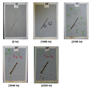
A multi-layer coating system contains several distinct failure planes. Separation can occur at the steel-primer interface, between coating layers, or through the body of one coating layer, called cohesive failure. Surface contamination, soluble salts, weak mill scale, improper recoat timing, ultraviolet exposure before overcoating, incompatible materials, trapped solvent, porosity, or incomplete cure can weaken different parts of the system.
A holiday exposes steel through a break in the coating. Buried or immersed steel may also use cathodic protection, a system that supplies electrons to the steel from a sacrificial metal or an external power source to reduce corrosion. Reactions at an exposed area can make the surrounding environment more alkaline and weaken the coating bond. The resulting loss of adhesion around the defect is called cathodic disbondment. ASTM G8, ASTM G42, ASTM D6676/D6676M, and AMPP TM0115 are among the methods used to evaluate this type of behavior under different test conditions.[25]

The location of separation is evidence. Bare steel beneath a detached coating points toward the steel-primer interface. Primer remaining on the steel while the next coat is missing indicates intercoat separation. Fracture through the body of a coating is cohesive failure. A failure investigation therefore records not only that a coating detached, but where the separation occurred and what material remained on each side of the interface.
Laboratory Validation of Materials and Protective Coatings
Laboratory testing is used to determine whether a material or coating system meets a defined requirement, to compare candidate systems under the same conditions, or to investigate why a field or production failure occurred. The purpose is to apply controlled stressors and measure the resulting changes—not to assume that a fixed number of laboratory hours represents a universal number of years in service.
A useful program begins with the substrate, manufacturing history, coating system, service environment, and governing specification. Specimens can then be evaluated using the exposure and measurement methods that address the actual performance question.
| Performance Question | Representative Methods | What the Program Can Measure |
|---|---|---|
| Corrosion resistance | ASTM B117, ISO 9227, ASTM G85, ASTM D5894 | Corrosion at defects, corrosion spreading from an intentional scratch (scribe creepage), rusting, blistering, and comparative coating breakdown |
| Moisture and immersion resistance | ASTM D2247, ASTM D4585/D4585M, ASTM D870, ISO 6270-1, ISO 2812-2 | Blistering, softening, adhesion change, underfilm corrosion, and barrier performance |
| Lining and process-fluid resistance | ASTM D6943, AMPP TM0174 | Liquid/vapor-zone response, one-sided exposure, and thermal-gradient effects |
| Cathodic-disbondment resistance | ASTM G8, ASTM G42, ASTM G95, ASTM D6676/D6676M, AMPP TM0115 | Disbondment growth around a coating holiday under controlled electrical and thermal conditions |
| Mechanical coating properties | ASTM D4541, ASTM D3359, ASTM D4060, ASTM D2794, ASTM D522/D522M | Adhesion, abrasion resistance, impact resistance, and flexibility |
| Weathering and appearance | ASTM G154, ASTM D4587, ASTM D523, ASTM D2244 | Chalking, cracking, gloss change, color change, and UV/moisture degradation |
| Failure characterization | Microscopy, cross sections, film-thickness measurement, FTIR, and targeted physical testing | Failure plane, layer structure, voids, thickness variation, material comparison, and evidence supporting probable failure mechanisms |
From Visible Defect to Probable Cause
A failure investigation connects the observed damage to the material, application, and service history. Record where the failure occurs, when it first appeared, which layers remain attached, and how affected areas differ from apparently sound areas. Patterns around edges, joints, heated regions, or wet locations can help guide the investigation. [26, ch. 7, pp. 135–140]
| Observed Defect | Questions to Resolve | Evidence to Examine |
|---|---|---|
| Blistering | Where is the separation? Are soluble contamination, retained solvent, or corrosion involved? | Blister liquid where available, the underside of the film, exposed substrate, layer structure, and service conditions |
| Intercoat peeling | Was the interface contaminated or affected by amine blush, recoat timing, or a weak underlying layer? | Both separated surfaces, material remaining on each side, application records, and comparison samples |
| Cracking | Which layers have fractured? Could restrained contraction, brittleness, film build, or substrate movement explain the pattern? | Cross sections, local thickness, crack distribution, underlying layers, and thermal or mechanical history |
| Softening | Is the coating incompletely cured, retaining solvent, or affected by absorbed liquid? | Exposure history, comparative chemical analysis, thermal behavior, and a suitably cured reference |
| Corrosion at edges or defects | Is protection locally thin, discontinuous, damaged, or poorly bonded? | Local cross sections, film continuity, the substrate-coating interface, and neighboring sound areas |
These questions guide test selection; the visible defect alone does not establish a unique cause. The approach combines field observations with microscopic, analytical, and physical evidence. [26, chs. 7–9]
Compare Failed Material with Suitable Reference Samples
Where available, collect material from failed and apparently intact locations, along with retained product or a coating prepared under documented conditions. Record the sampling location and preserve the layer sequence and exposed failure surfaces. A material detected in failed paint is not automatically the cause: it may also occur in sound paint, or it may have entered after damage developed. Comparisons are most useful when sample preparation and analytical conditions are consistent and differences in exposure history are considered. [26, ch. 7; sec. 8.2.4; sec. 8.4.3]
Match the Analytical Method to the Question
Microscopy can locate the failure plane, measure individual layers, and reveal pores or cracks. Infrared spectroscopy measures which infrared wavelengths a material absorbs. The absorption pattern can help identify binder chemistry and compare deposits or chemical changes. Chromatography separates substances in a sample so they can be identified or measured. Depending on the suspected mechanism, different forms of chromatography can investigate retained solvents or dissolved salts. Differential scanning calorimetry (DSC) measures heat-flow changes during controlled heating and can help compare glass-transition behavior and residual curing reactions. These methods answer different questions and are selected according to the evidence needed. [26, secs. 8.1–8.7]
Interpreting Cure Evidence
A low glass-transition temperature does not, by itself, establish under-cure. Absorbed moisture and retained solvents can also lower the measured transition. Conversely, heating a sample during drying or analysis can advance its cure and change the result. Interpretation should account for sample conditioning, thermal history, and comparison with a suitable reference coating. [26, secs. 8.7.2–8.7.3, pp. 250–258]

GPI Labs

GPI Labs

GPI Labs
Validate a Material or Coating System with GPI Labs
GPI Labs supports independent materials and coating validation from specimen preparation through controlled exposure, physical-property testing, microscopy, analytical characterization, failure investigation, and reporting. Send the material or coating system, the governing specification, the service condition, and the question the program needs to answer. GPI can help define a test scope that measures the relevant performance rather than applying an unrelated exposure by default.
References
- World Steel Association, “What Is Steel?” https://worldsteel.org/about-steel/what-is-steel/
- U.S. Department of Energy, “Iron and Steel Manufacturing.” https://www.energy.gov/cmei/ito/iron-and-steel-manufacturing
- U.S. Department of Energy, Lead and Zinc, Energy and Environmental Profile of the U.S. Mining Industry. https://www.energy.gov/sites/prod/files/2013/11/f4/lead_zinc.pdf
- International Aluminium Institute, “Primary Production.” https://alustory.international-aluminium.org/primary-production/
- American Cement Association, “How Cement Is Made.” https://www.cement.org/cement-concrete/how-cement-is-made/
- Association for Materials Protection and Performance, “What Is Corrosion?” https://www.ampp.org/technical-research/what-is-corrosion
- Dwivedi, D., Lepkova, K., and Becker, T., “Carbon Steel Corrosion: A Review of Key Surface Properties and Characterization Methods,” RSC Advances 7 (2017): 4580-4610. https://doi.org/10.1039/C6RA25094G
- Galster, S., and Helmreich, B., “Copper and Zinc as Roofing Materials – A Review on the Occurrence and Mitigation Measures of Runoff Pollution,” Water 14, no. 3 (2022): 291. https://doi.org/10.3390/w14030291
- Metal Construction Association, “Dissimilar Metal Corrosion in Roofing Installations.” https://www.metalconstruction.org/view/download.php/online-education/education-materials/roofing-educational-materials/dissimilar-metal-corrosion-in-roofing-installations
- Parangusan, H., et al., “A Review of Passivity Breakdown on Metal Surfaces: Influence of Chloride- and Sulfide-Ion Concentrations, Temperature, and pH,” Emergent Materials 4 (2021): 1187-1203. https://doi.org/10.1007/s42247-021-00194-6
- Federal Highway Administration, “Appendix A: Distress Mechanisms,” Guidelines for Detection, Analysis, and Treatment of Materials-Related Distress in Concrete Pavements, FHWA-RD-01-163. https://www.fhwa.dot.gov/publications/research/infrastructure/pavements/pccp/01163/app.cfm
- Pommersheim, J. M., and Clifton, J. R., Models of Transport Processes in Concrete, NISTIR 4405 (1990). https://nvlpubs.nist.gov/nistpubs/Legacy/IR/nistir4405.pdf
- Ali, M., et al., “A Review on Chloride-Induced Corrosion in Reinforced Concrete,” Heliyon 10 (2024). https://pmc.ncbi.nlm.nih.gov/articles/PMC11580005/
- Mills, D. J., and Jamali, S. S., “Advances in Corrosion Protection by Organic Coatings,” Progress in Organic Coatings 95 (2016): 26-37. https://nectar.northampton.ac.uk/id/eprint/9268/
- NASA Kennedy Space Center Corrosion Technology Laboratory, “Coatings Data” and NASA-STD-5008. https://public.ksc.nasa.gov/corrosion/coatings-data/
- American Galvanizers Association, “Batch Hot-Dip Galvanizing.” https://galvanizeit.org/corrosion/corrosion-protection/zinc-coatings/batch-hot-dip-galvanizing
- ASTM International, ASTM A123/A123M-24, Standard Specification for Zinc (Hot-Dip Galvanized) Coatings on Iron and Steel Products. https://store.astm.org/a0123_a0123m-24.html
- GPI Labs, “Protective Coating & Lining Testing for Water and Wastewater Infrastructure.” https://gpilabs.com/services/water-wastewater-infrastructure-testing/
- American Water Works Association, AWWA C210-24, Liquid-Epoxy Coatings and Linings for Steel Water Pipe and Fittings. https://store.awwa.org/AWWA-C210-24-Liquid-Epoxy-Coatings-and-Linings-for-Steel-Water-Pipe-and-Fittings
- ASTM International, ASTM D7803-25, Standard Practice for Preparation of Zinc (Hot-Dip Galvanized) Coated Iron and Steel Product and Hardware Surfaces for Powder Coating. https://store.astm.org/d7803-25.html
- International Organization for Standardization, ISO 12944-6:2018, Paints and Varnishes – Corrosion Protection of Steel Structures by Protective Paint Systems – Part 6: Laboratory Performance Test Methods. https://www.iso.org/standard/51378.html
- American Galvanizers Association, “How Does Galvanizing Protect Steel from Corrosion?” https://galvanizeit.org/inspection-course/course-navigation/frequently-asked-questions
- Sabet-Bokati, K., and Plucknett, K., “Water-Induced Failure in Polymer Coatings: Mechanisms, Impacts and Mitigation Strategies – A Comprehensive Review,” Polymer Degradation and Stability 230 (2024): 111058. https://doi.org/10.1016/j.polymdegradstab.2024.111058
- Zargarnezhad, H., Asselin, E., Wong, D., and Lam, C. N. C., “A Critical Review of the Time-Dependent Performance of Polymeric Pipeline Coatings: Focus on Hydration of Epoxy-Based Coatings,” Polymers 13, no. 9 (2021): 1517. https://doi.org/10.3390/polym13091517
- GPI Labs, “Pipeline Materials, Coating & Corrosion Testing Services.” https://gpilabs.com/services/pipeline-materials-coating-corrosion-testing/
- Weldon, Dwight G. Failure Analysis of Paints and Coatings. Revised edition. Chichester: John Wiley & Sons, Ltd., 2009. ISBN 978-0-470-69753-5. Relevant material: Chapter 1, coating formulation; Chapter 2, adhesion, permeability, stress, and blistering; Section 5.3.2, epoxy failure modes; Section 5.14, powder coatings; Chapter 7, field methods; Chapter 8, analytical methods; and Chapter 9, physical methods. Page references above use the book’s printed pagination.